Heterogeneous Substrate Core Lamination Dynamics and Resin Gradient Phase Extraction
Heterogeneous core lamination requires synchronized thermal ramps to align flow windows and prevent resin phase extraction along substrate interfaces.
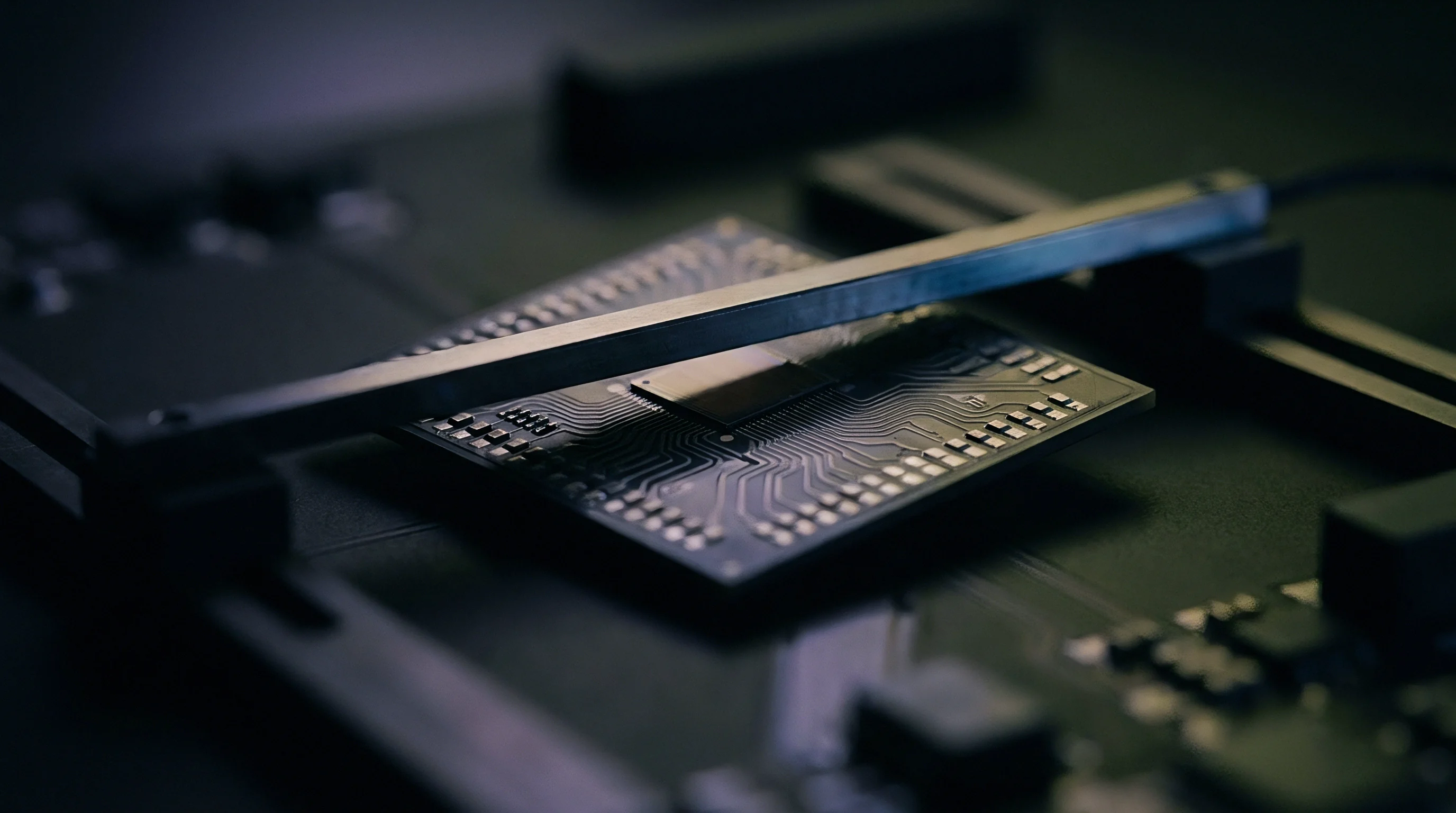
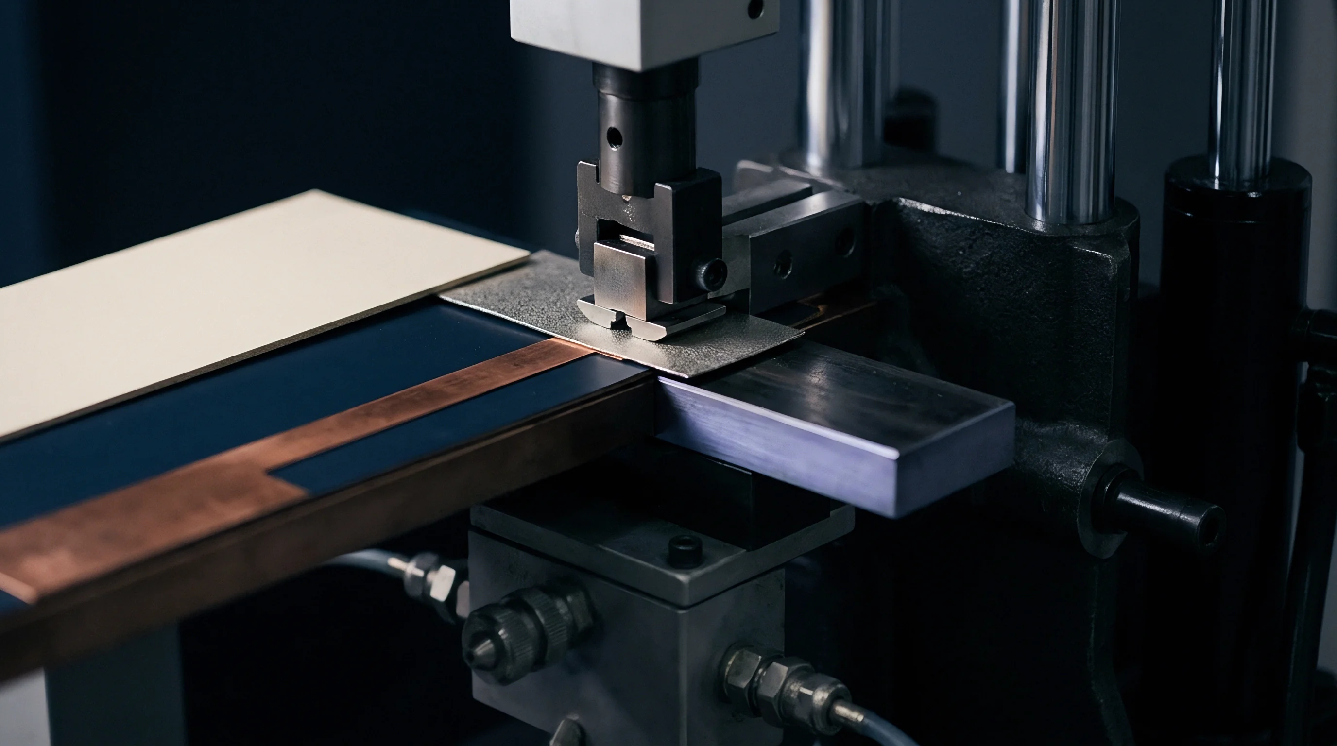
Melt
Co-laminating low-loss hydrocarbon ceramics with high-performance polyimides introduces thermodynamic mismatches that generate non-uniform rheological shear along core boundaries. If dissimilar prepreg systems are pressed against rigid inner-layer cores at ramp rates above three degrees Celsius per minute, their viscosity curves diverge: high-Tg FR-4 matrices reach gelation while softer fluoropolymer or hydrocarbon systems remain near their fluid minimums. Pressure gradients across the platen package then force liquid resin out of high-density copper areas into low-density relief zones.
This resin migration leaves dry glass filaments exposed on core faces and skews local fiber-to-resin ratios.
Phase extraction occurs as low-molecular-weight epoxy oligomers and crosslinkers segregate from the bulk matrix. Because polymerization rates differ across the laminate interface, rapid matrix softening allows uncured fractions to migrate into micro-voids along the foil surface, building up a resin-rich layer with compromised mechanical and electrical characteristics. This secondary phase separation shifts the dielectric constant along the signal path, throwing off impedance targets in high-frequency transmission lines while degrading inter-laminar shear strength at the depleted interface.
Viscosity mismatches across core interfaces drive low-molecular-weight resin fractions into internal foil relief structures.

Rheological Asymmetry in Hybrid Stackups
Viscosity transitions between adjacent prepreg plies set up localized pressure drops across the bond line. Hydrocarbon resins cure via free radicals, whereas standard epoxy networks depend on amine or anhydride crosslinking reactions. In a heterogeneous stackup, those softening points rarely synchronize.
The lower-viscosity material moves prematurely once platen force takes hold, bleeding into clearance voids around copper power planes and stripping resin volume away from trace corners.
Differing glass transition temperatures worsen layer movement as the press cools. Because cores shrink asynchronously, the stiffer substrate imparts residual shear stress to the softer interface, seeding micro-fractures along the boundary layer. Fluid resin can also pull reinforcement yarns off-axis, distorting the glass weave and compromising registration between drill targets and inner-layer pads as the cores shift laterally.
Mismatched flow rates across dissimilar material boundaries eventually manifest as delamination during assembly reflow, scrapping entire panel runs.

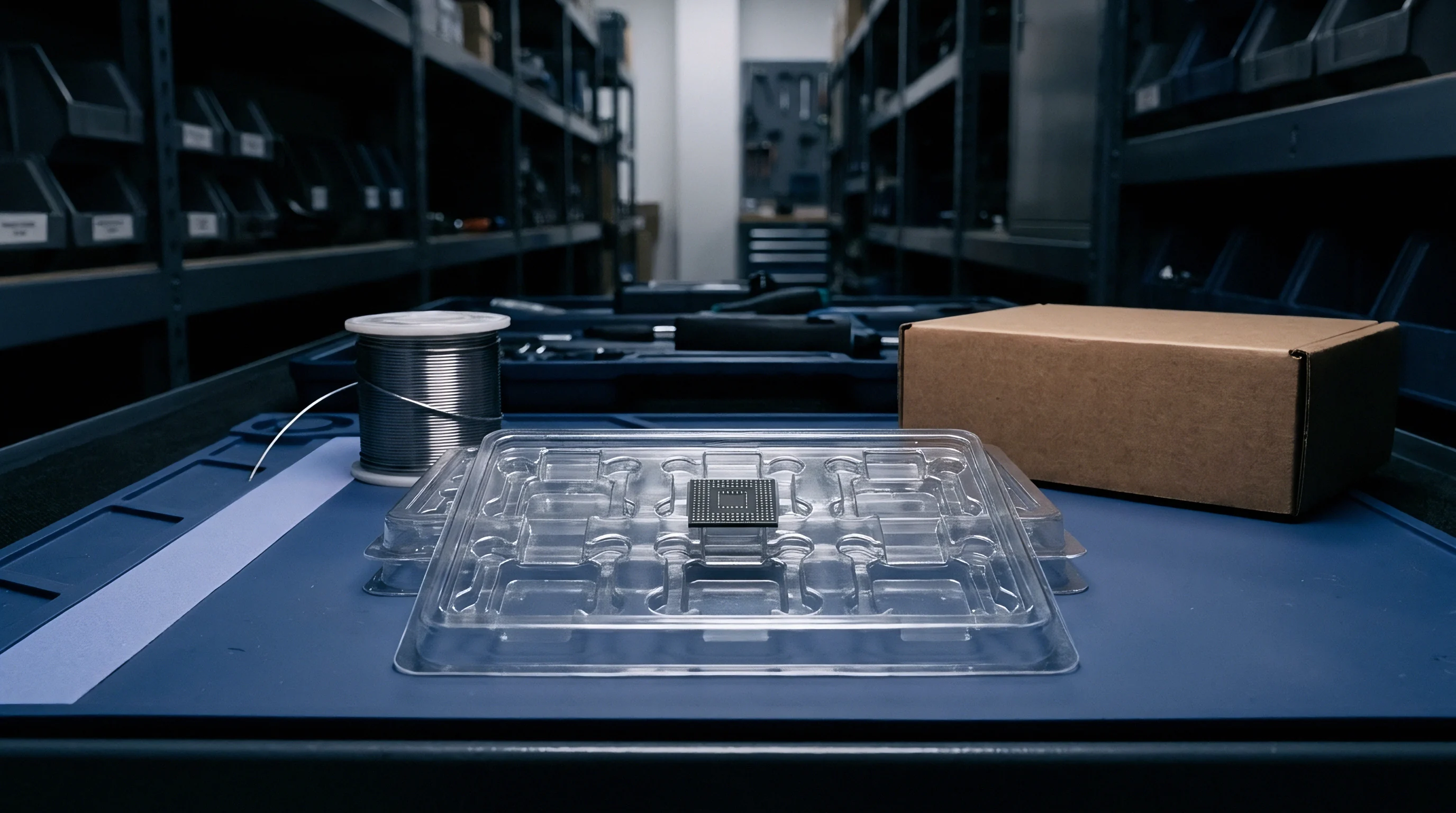
Pressure
Force distribution through a multi-platen hydraulic press changes significantly when soft fluoropolymer cores meet rigid thermoset glass matrices. Nominal platen pressure translates into uneven compaction stress across the stackup: high-density trace features take the brunt of the load, while clearance voids see far less compaction. As viscosity falls before polymerization takes hold, resin migrates toward areas of low hydrostatic pressure, carrying low-molecular-weight components out of the bulk polymer matrix.
This gradient extraction upsets chemical stoichiometry at the core-prepreg junction. Low-viscosity fractions leach catalyst additives away from the bulk core face, leaving depleted zones that fail to crosslink fully and suffer a fifteen to twenty-five degrees Celsius drop in glass transition temperature. Voids multiply near the laminate boundaries, and during wet surface finishing, these resin-starved cavities take on moisture that later drives electrochemical migration under bias.
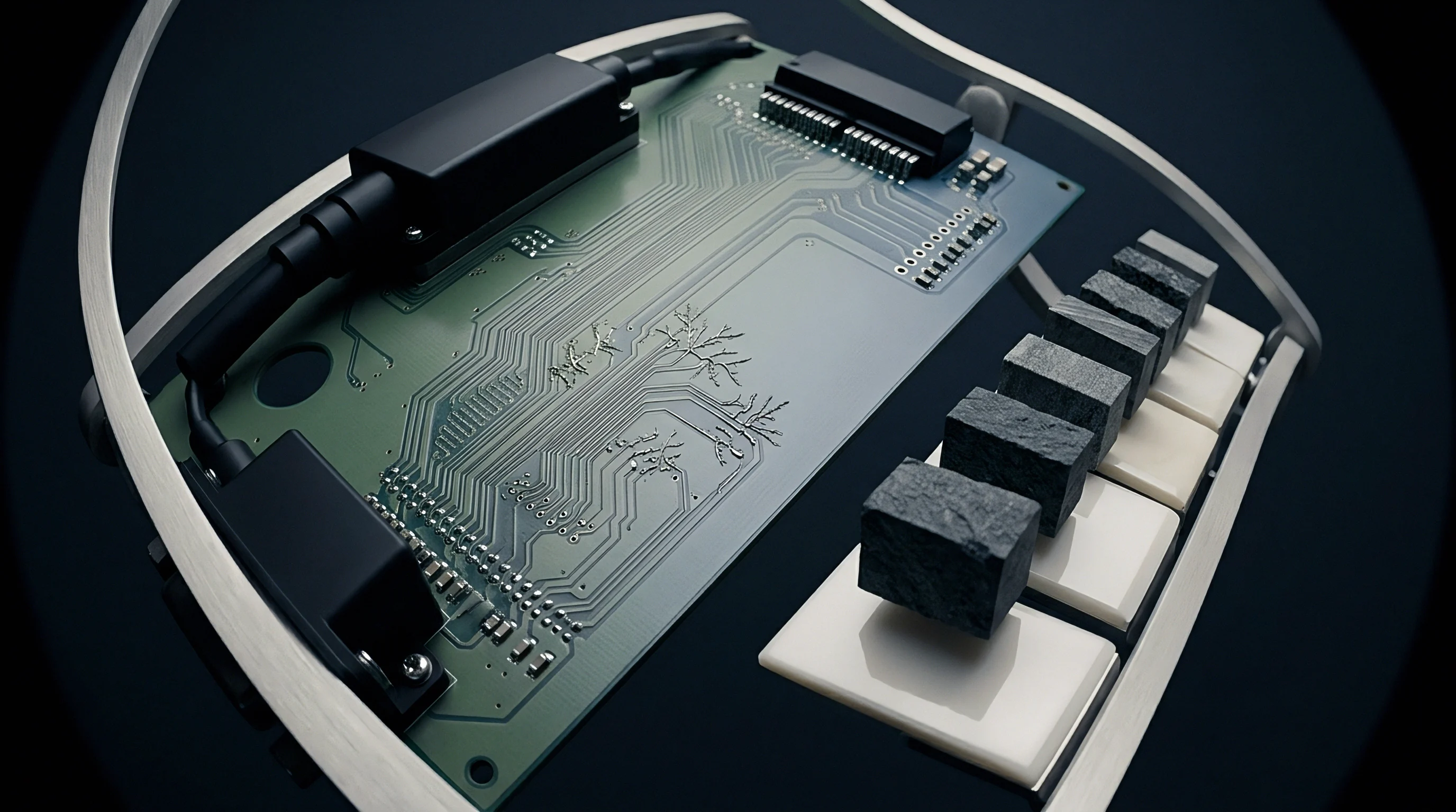
Force Distribution across Core Interfaces
During the initial ramp, compaction stress peaks at high-density weave intersections, where heavy glass yarns bite into softer core substrates and cause localized thinning. These steep pressure gradients drive lateral flow ~ especially in thinner prepregs, which exhibit much higher squeeze-out rates. The table below outlines the rheological behavior and minimum viscosity parameters for common heterogeneous core and prepreg combinations evaluated under standard vacuum-hydraulic press cycles.
| Laminate Grade | Resin System Type | Viscosity Minimum (Pa.s) | Gelation Temperature (deg C) | Flow Window (s at 3 deg C/min) |
|---|---|---|---|---|
| Hydrocarbon Ceramic | Thermoset Hydrocarbon | 140 | 162 | 110 |
| High-Tg FR-4 | Polyfunctional Epoxy | 18 | 138 | 210 |
| PTFE Filled Glass | Thermoplastic Fluoropolymer | 850 | 280 | 45 |
| Non-MDA Polyimide | Polyimide Thermoset | 120 | 195 | 160 |

Visco-Elastic Flow Differentials
Gelation kinetics dictate whether resin properly fills internal copper clearances or sheds low-molecular-weight fractions into the surrounding structure. If a fast-reacting prepreg hardens before a lower-viscosity core completes hydraulic filling, air pockets remain pinned along signal trace sidewalls. Vacuum pressure pulls out these entrained volatiles, though pulling vacuum too aggressively can strip lighter solvents from modified resin systems and seed micro-porosity through the bond line.
Tailoring the hydraulic force profile helps curb matrix migration across composite boundaries. Fabricators rely on multi-stage pressure profiles to balance flow rates: a gentle kiss pressure during the initial ramp promotes uniform heat transfer without triggering excessive squeeze-out, followed by full compaction pressure once every resin system in the stackup has entered its shared flow window.
- Interfacial resin depletion occurs when high-viscosity prepregs squeeze lower-viscosity core matrices away from high-density copper features during initial hydraulic compaction.
- Glass weave telegraphing arises as glass bundles press into softened core faces, causing periodic dielectric thickness variations along transmission lines.
- Volatile void entrapment stems from premature surface gelation that seals internal escape pathways before vacuum systems exhaust low-boiling-point resin constituents.
- Stoichiometric migration develops when active curing agents dissolve into adjacent liquid phases, leaving unreacted resin fractions along boundary zones.
Internal voiding can result from improper press acceleration during fabrication or from unaddressed formulation mismatches between resin systems.


Bleed
When thermal ramps surpass five degrees Celsius per minute, low-viscosity resin fractions bleed laterally along the glass yarns, distorting clearance openings around high-voltage vias and shifting core boundaries. Microsections show that this phase extraction produces a density gradient across the dielectric junction, so permittivity shifts along a continuous curve rather than stepping cleanly between materials.
This separation collects uncrosslinked oligomers directly against the copper foil treatment, weakening bond strength to the oxide layer. During thermal cycling, differential thermal expansion generates shear stress along the compromised boundary and triggers delamination, while outer-layer traces suffer impedance ripple from the uneven dielectric foundation beneath them.
IPC-4101 Clause 3.8.1 rejects laminate core lots displaying resin phase separation wider than fifty micrometres along internal interfaces.

Will Differential Thermal Expansion Cause Interfacial Phase Extraction?
Stresses mounting across heterogeneous core boundaries tend to push uncrosslinked epoxy oligomers out of the matrix before full cure is achieved. Because the substrates have different glass transition temperatures, a soft hydrocarbon core expands rapidly in the Z-axis while an adjacent polyimide core stays rigid. That volumetric mismatch creates localized pressure spikes that squeeze lower-molecular-weight fractions directly out of the curing thermoset matrix.
As resin bleeds off the core surface, bare glass micro-filaments make direct contact with the copper foil teeth, degrading mechanical adhesion. During blind via formation, laser beams scatter off these exposed filaments to leave ragged hole walls and irregular geometry. Desmear chemistries then attack the resin-depleted boundary aggressively, undercutting pads and causing folds during copper electrodeposition.
- Bake inner cores at one hundred and fifty degrees Celsius for four hours to eliminate moisture and residual solvents before lay-up assembly.
- Apply silane coupling agents to exposed copper clearance zones to stabilize the chemical bond between mismatched resin interfaces.
- Ramp platen temperature at one point two degrees Celsius per minute to synchronize minimum viscosity windows across all hybrid core layers.
- Hold hydraulic pressure at zero point five megapascals during initial resin liquefaction to limit lateral fluid displacement before applying full compaction force.

Quantifying the Gradient Dielectric Shift
Energy-dispersive X-ray spectroscopy on cross-sections reveals resin density variations extending as far as eighty micrometres from the foil boundary. These leached low-molecular-weight fractions alter local permittivity, shifting propagation velocities across differential traces and introducing unwanted phase skew on high-speed digital buses.
| Distance from Core Boundary (um) | Extractable Low-MW Fraction (%) | Local Resin Density (g/cm3) | Local Dielectric Constant (10 GHz) | Local Dissipation Factor (10 GHz) |
|---|---|---|---|---|
| 0 (Interface Boundary) | 14.2 | 1.12 | 3.82 | 0.0085 |
| 20 | 9.8 | 1.18 | 3.65 | 0.0062 |
| 40 | 5.1 | 1.22 | 3.52 | 0.0041 |
| 60 | 2.3 | 1.25 | 3.48 | 0.0038 |
| 80 (Bulk Material) | 1.1 | 1.26 | 3.46 | 0.0037 |
Assuming a static dielectric constant in stackup calculations leads to flawed impedance models for multi-gigahertz work. In a twelve-layer hybrid board pairing hydrocarbon RF cores with high-Tg FR-4 digital layers, a nominal fifty-ohm trace measured at forty-six point two ohms once resin extraction took place. That six percent impedance drop comes straight from the dense resin boundary layer formed alongside the RF conductor, where solder mask clearance also demands tight tolerance.
Interfacial resin depletion increases localized loss tangent values by as much as one hundred and thirty percent within forty micrometres of the core boundary. This accelerates high-frequency signal attenuation and concentrates heat along narrow conductor channels, compounding thermal degradation risks during sustained high-power operation.
IPC-6012 Section 3.3.2 specifies a maximum allowable core void size of 75 micrometres, forcing lot rejection whenever resin phase extraction leaves unreinforced dielectric cavities along trace walls.

Kinetics
Cure progression determines how long resin has to segregate. Differential scanning calorimetry traces show pronounced differences in crosslinking rates among epoxy, polyimide, and hydrocarbon systems. As heat penetrates the stackup, low-molecular-weight fractions liquefy first, with the kinetic reaction order dictating how fast polymerization takes over.
A rapid crosslinking reaction shuts the flow window quickly, arresting phase extraction before it spreads.
Sluggish reaction kinetics, by contrast, keep the resin at low viscosity under pressure for far too long, allowing fluid matrix to bleed toward the panel perimeter. That squeeze-out pulls structural glass yarns flush against internal copper features, bringing signal traces into direct contact with reinforcement bundles and creating glass weave skew as differential pairs run across alternating knuckles and resin pockets.
At a heating rate of 3 degrees Celsius per minute, hydrocarbon prepreg reaches its minimum viscosity of 140 Pascal-seconds at 162 degrees Celsius.
Thermal Cycle Calibration and Isothermal Holds
Staging platen temperatures with intermediate plateaus stabilizes viscosity across mismatched prepreg packages, eliminating internal thermal gradients across multi-opening press loads. Because outer panels in a press book heat up faster than interior panels, isothermal dwells bring core temperatures into balance so that flow windows align before full hydraulic pressure arrives.
Chamber vacuum must remain below twenty millibars through the initial heating phase to suppress moisture vaporization. Any water vapor trapped inside low-viscosity resin pockets will expand as temperatures rise, creating microscopic blister voids that slash dielectric breakdown strength and trigger failures during high-voltage isolation screening.
- Load press books into multi-platen vacuum chambers pre-heated to sixty degrees Celsius.
- Evacuate press chamber to fifteen millibars absolute pressure for twenty minutes prior to heating.
- Ramp temperature at one point eight degrees Celsius per minute to one hundred and thirty-five degrees Celsius.
- Maintain isothermal hold for thirty minutes under zero point six megapascals hydraulic pressure.
- Increase hydraulic pressure to two point one megapascals and ramp temperature to one hundred and ninety-five degrees Celsius.
- Hold peak temperature and pressure for ninety minutes to achieve complete polymer crosslinking.
- Cool assembly under full compaction pressure at two point five degrees Celsius per minute until temperature drops below seventy degrees Celsius.

Differential Scanning Calorimetry Verification
Enthalpy curves taken from cured coupons verify crosslinking across both thermoset and thermoplastic phases, flagging unreacted monomer residue whenever local stoichiometry drifts. Residual oligomers behave like plasticizers in the cured matrix, depressing key thermal resistance benchmarks such as T260, T288, and time-to-delamination during solder reflow.
Re-tuning cure profiles helps ensure that interface zones reach thermal stability. Dynamic mechanical analysis frequently reveals depressed glass transition values in regions hit by phase extraction, where severe registration shifts can damage fine lines. Boards subjected to multiple reflow cycles risk inter-laminar separation if interfacial transition temperatures fall near or below operational thresholds.
Whether secondary post-cure baking can fully stabilize crosslinking in extracted low-molecular-weight resin gradients without degrading adjacent copper foil adhesion remains unproven in high-frequency field environments.

Margin
Financial losses on hybrid core builds trace largely to localized impedance variations from resin depletion. Panel yields collapse whenever edge bleed creeps past set tolerances: perimeter sections see steep hydrostatic pressure gradients that siphon resin out of active array areas, leaving structurally weaker borders and driving scrap rates up when outer board traces wander outside the standard ten percent impedance window.
Material utilization suffers when wide border dams are introduced to block resin migration and shield active circuits from edge pressure drops. With soft core substrates commanding upwards of two hundred dollars per square metre, sacrificing panel real estate to flow-control structures imposes an immediate financial penalty.
Wider picture-frame dams on internal layers restrict lateral resin displacement across soft core substrates.
Panel Array Edge Waste and Boundary Dams
Running copper picture frames around the perimeter of internal core layers establishes a barrier against excessive resin escape, while copper thieving balances hydraulic pressure across the panel face. These dense copper borders contain the lower-viscosity resin within active board outlines, though the required dam width scales upward with the viscosity gap between adjacent prepreg plies.
| Core Combination | Dam Clearance (mm) | Usable Array Area (%) | Panel Yield Rating (%) | Landed Board Unit Cost ($) |
|---|---|---|---|---|
| Standard FR-4 Core Pair | 5.0 | 78.5 | 94.2 | 12.40 |
| Hydrocarbon / FR-4 Hybrid | 12.5 | 68.2 | 82.1 | 28.90 |
| PTFE / Polyimide Hybrid | 20.0 | 58.4 | 69.5 | 64.10 |
| Data derived from standard 18×24 inch production panels using 1-ounce internal copper layers and 1.6 mm finished board thickness under IPC Class 3 inspection criteria. | ||||

Yield Mechanics and Commercial Risk Distribution
Standard scrap allowances in master supply agreements rarely absorb the steep price of specialized microwave laminates. Fabricators consequently price extra margin into unit quotes on complex heterogeneous stackups, anticipating that impedance shifts and signal degradation from resin extraction will require supplemental panel screening ~ adding as much as eighteen percent to baseline quality assurance expenses across a production lot.
Dialing in lamination parameters protects gross margins by recovering usable panel area and cutting electrical fallout. Engineering and procurement teams often avoid cost spikes by locking in flow-restrictive prepreg grades during initial stackup development, curbing phase separation early and preserving uniform dielectric performance across the working area.
Widening outer dams protects internal dielectric uniformity whenever soft core materials run against high-pressure glass prepregs.