Hybrid Probing Regimes to Unmask Hidden Ball Grid Array Defects
Combining IEEE 1149.6 boundary scan vectors with deflection-assisted flying Kelvin probes isolates unmasked BGA head-in-pillow defects down to 4.5 micro-ohms.
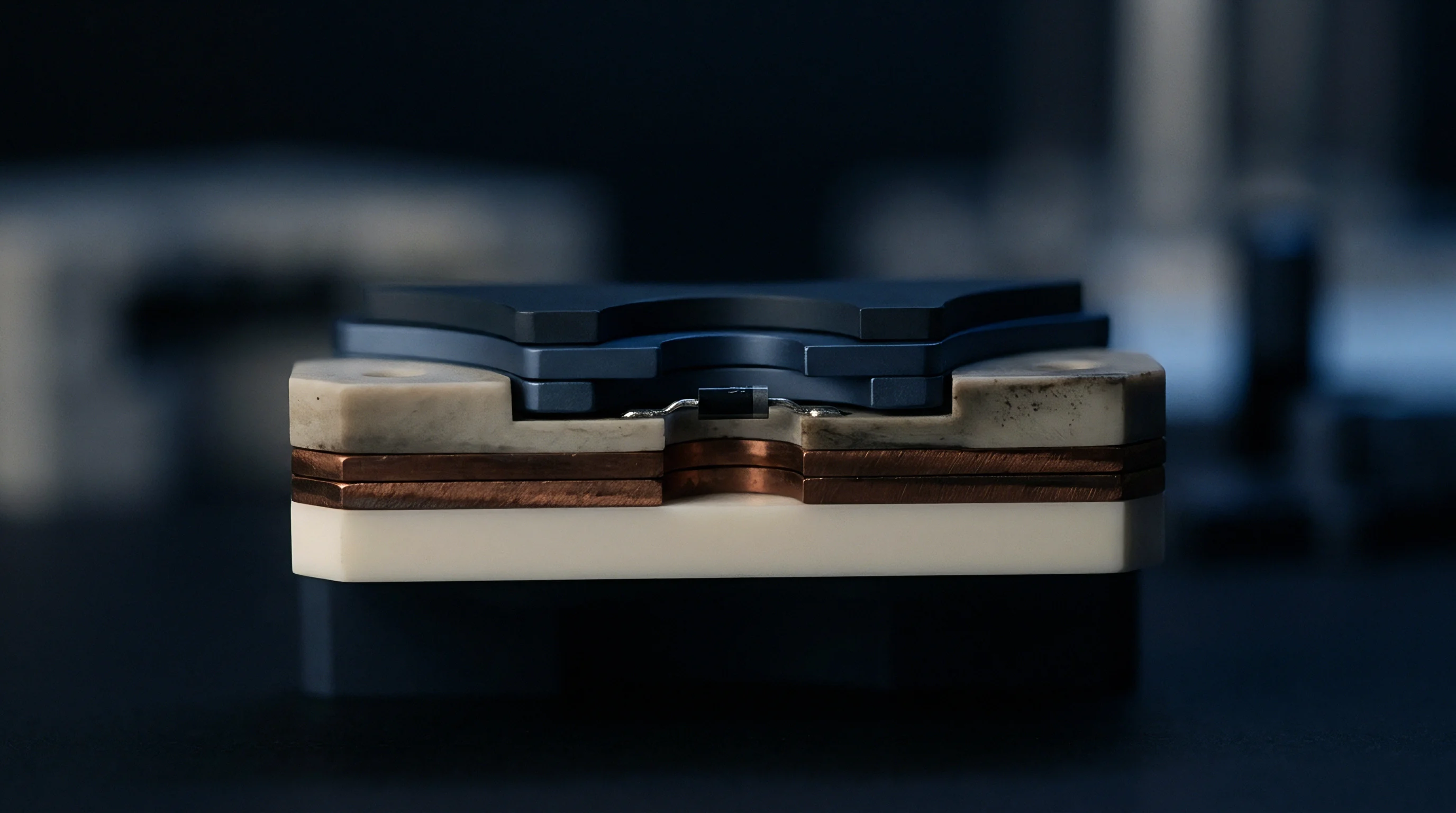

Access
Single-regime test architectures often return false pass results on printed circuit board assemblies with ball grid arrays. On fine pitches from 0.8 millimeters down to 0.4 millimeters, package density prevents physical probe tips from reaching every signal pin. High-pin-count silicon devices also present internal power grids where dozens of solder balls share common copper planes, leaving individual open joints hidden behind low-resistance parallel paths during standard DC resistance checks.
Catching defects under zero-clearance ball grid arrays requires combining bed-of-nails fixtures, flying probe vectors, and IEEE 1149.1 or IEEE 1149.6 boundary scan registers into a single sequence. Defect modes like head-in-pillow ~ where the solder ball and target pad melt independently without fusing across their oxide interface ~ maintain physical contact while the board sits at rest. The joint conducts direct current normally under static conditions, staying hidden until thermal or mechanical stress opens the gap in the field.
| Defect Mechanism | Flying Probe Alone | In-Circuit Test Alone | Boundary Scan Alone | Hybrid Flying Probe and Boundary Scan |
|---|---|---|---|---|
| Head-In-Pillow Intermittency | 12 percent | 18 percent | 0 percent | 88 percent |
| Micro-Voiding Above 30 Percent | 0 percent | 0 percent | 0 percent | 45 percent |
| Solder Bridging under BGA Body | 95 percent | 99 percent | 98 percent | 100 percent |
| Single Ball Power Grid Open | 4 percent | 8 percent | 0 percent | 91 percent |
| Pad Cratering Fracture | 15 percent | 22 percent | 5 percent | 94 percent |
Balancing test coverage against board density when allocating test points sets the residual risk level. Adding physical probe targets to every net on a 1,500-ball package degrades signal integrity on differential lines running above 10 gigabits per second. High-speed nets must rely on non-contact boundary scan logic, leaving flying probes to access perimeter pads and reachable bypass capacitors for analogue testing at peripheral nodes.
A hybrid probe routine combining boundary scan logic state control with analogue nodal measurement isolates high-resistance joint anomalies down to 1.2 ohms above nominal trace impedance.
Test access strategies that leave digital nodes unprobed without boundary scan fallback produce escape rates over 450 defects per million units shipped. Warranty reserves absorb the hit, as field returns, freight, and root-cause failure analysis wipe out whatever unit cost savings were gained by skipping physical test points.

Strain
Applying dynamic mechanical force to a board during electrical test alters the physical gap at unbonded solder joints. Head-in-pillow defects and intermetallic micro-cracks maintain physical contact when relaxed, passing standard low-voltage electrical continuity checks. Controlled board deflection during probing flexes the substrate, pulling fractured joints apart and forcing an immediate open-circuit reading in the receiver loop.
Bed-of-nails fixtures with pneumatic push rods or automated flying probes fitted with force-controlled Z-axis actuators apply controlled deformation cycles during test execution. Local strain around the ball grid array perimeter must stay strictly between 300 and 500 microstrain ~ enough to open weak joints without causing pad cratering in good ones. Deflection changes resistance across defective joints by three orders of magnitude, turning intermittent contact into a hard failure for the measurement engine.
- Head-in-pillow interface separations unmask when mechanical deflection pulls a warped board corner away from the package substrate.
- Brittle intermetallic micro-fractures at the package interface produce high-speed resistance spikes during cyclic mechanical vibration.
- Pad cratering trace tears beneath the outer solder ball row open under positive substrate bending moments.
- Non-wet open joints caused by organic solderability preservative degradation trigger instant logic low transitions during active boundary scan loopback.
Deflection testing requires active strain gauge calibration on the fixture. Mechanical stress must remain within copper foil tear limits set by IPC assembly standards. The fixture holds the board flat for baseline measurements, applies controlled force during high-speed continuity checks, and relaxes the assembly back to its nominal state.
Strain cycling catches latent assembly defects before shipment; testing without mechanical displacement leaves hidden fractures intact.
Applying too much deflection creates new fractures in sound solder joints while hunting for existing ones.
Boundary
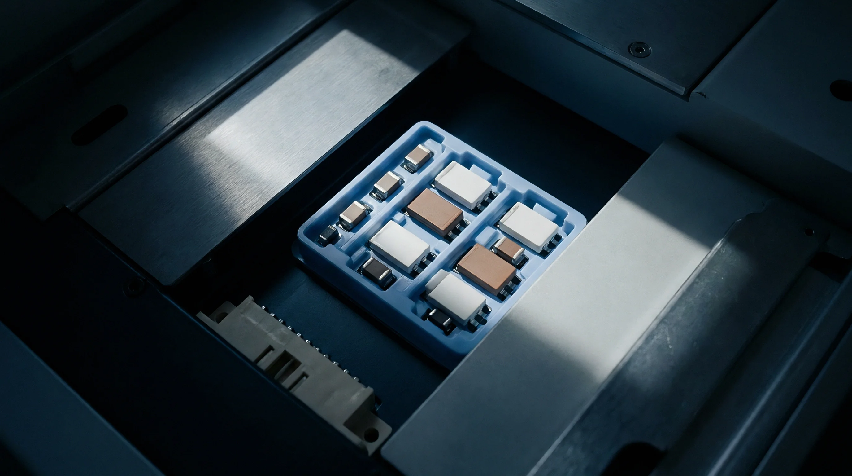
Shift registers embedded inside silicon integrated circuits serve as virtual probe points for package ball pins. The IEEE 1149.1 boundary scan standard uses internal instruction and data registers to drive and capture logic states across BGA interconnects without physical test pins. This bypasses the physical access constraints of dense ball arrays, turning hidden solder connections into serial data shifted out through a four-wire Test Access Port.

Does Boundary Scan Alone Catch Head in Pillow Defects?
Standard digital boundary scan logic verifies state transitions across input and output cells, catching complete opens and direct shorts. However, a head-in-pillow joint in physical contact still conducts enough current to pass logic high and low states at low test frequencies. The receiver register sees valid thresholds despite the oxide layer inside the joint, returning a false pass to the test controller.
Detecting these high-resistance defects requires AC-coupled IEEE 1149.6 testing or pairing boundary scan states with analogue flying probe measurements.
| Interconnect Domain | Physical Vector | Stimulus Signal | Response Evaluator | Target Failure Mode |
|---|---|---|---|---|
| Low-Speed Digital I/O | Boundary Register | DC Logic Pattern | Boundary Capture Cell | Complete Open, Short |
| AC-Coupled High-Speed I/O | IEEE 1149.6 Receiver | Pulse Transition | AC Boundary Cell | Capacitor Open, Head-in-Pillow |
| Parallel Power Grid Pins | Flying Probe Vector | Sub-Ohm Delta Pulse | Precision Voltmeter | Single Ball Power Open |
| Analogue Peripheral Pin | In-Circuit Probe | Guarded AC Frequency | Analogue Measurement Unit | Impedance Drift, Partial Bridge |
Extending boundary scan across high-speed differential channels with IEEE 1149.6 introduces pulse-based transition analysis. High-frequency pulses injected by transmitter cells decay rapidly when passing through resistive head-in-pillow oxide layers or cracked AC-coupling capacitors. The receiver’s internal hysteresis captures the distorted waveform, flagging faults on channels that pass standard DC boundary tests.
Contractual acceptance under IPC-A-610 Class 3 specifications mandates zero unverified BGA pins across active medical and aerospace board assemblies.
Combining the IPC-9252 standard for bare-board electrical testing with IEEE 1149.1 verification separates trace defects from assembly solder faults. If technical audit dossiers lack complete boundary scan coverage reports, European regulatory bodies can challenge low-voltage directive compliance, leading to immediate sales holds.
Contact
High-density micro-ohmic measurements rely on dual-sided flying probe systems operating with micro-gram force control. Soft-landing tungsten-rhenium tips pierce solder mask openings and surface finishes without damaging underlying copper pads. Measuring resistance shifts down to 10 milliohms across parallel BGA power planes catches single-ball open circuits that standard bed-of-nails fixtures miss.
- Position the target assembly inside the dual-sided flying probe chamber and run optical laser alignment to establish board origin coordinates.
- Drive probe needles to primary bypass capacitor pads linked directly to internal BGA power and ground planes.
- Inject a 100-milliampere constant current pulse across the power rail while measuring the voltage drop across opposing access points.
- Shift boundary scan registers simultaneously to force internal silicon drivers into high-impedance tri-state mode.
- Record the differential voltage response, compare sub-milliohm readings against baseline finite-element simulations, and log the resistance delta.
On a high-density graphics processing board with a 1,156-ball BGA device, 280 solder balls connect in parallel to a 0.9-volt high-current core rail. Fully bonded, baseline loop resistance across the power plane measures 1.25 milliohms. A single open solder ball near the center of the array increases total plane resistance by roughly 4.5 micro-ohms ~ a delta invisible to standard two-wire meters.
A four-wire Kelvin flying probe applying a 1.000-ampere current pulse measures 1.250 millivolts across a healthy power plane. If two solder balls separate from head-in-pillow defects, current density shifts and elevates the Kelvin reading to 1.259 millivolts. Tightening the test limit window to plus or minus 5 micro-volts around the simulation baseline isolates those open parallel joints reliably.
Single-ball power grid opens escape standard bed-of-nails fixtures due to low-resistance copper plane current distribution.
Bypassing Kelvin measurements on parallel power balls lets unmasked power-plane necking failures reach customers, resulting in thermal throttling and premature field returns.

Guard
Active circuit guarding removes sneak current paths during analogue measurements under ball grid arrays. When probing passive components connected to BGA signal pins, ESD protection diodes and low-resistance internal pull-ups create parallel paths in the silicon. Unguarded probes measure the combined impedance of the component and internal junctions, masking missing or wrong passive values.
| Circuit Node Topology | Guarding Strategy | Primary Isolation Standard | Compliance Evidence Output |
|---|---|---|---|
| BGA Pull-Up Resistor Array | Active Power Rail Clamp | IPC-9252 Class 3 | Sub-Ohm Analogue Guard Log |
| Differential High-Speed Pair | Tri-State Boundary Cell | IEEE 1149.6 Clause 4 | AC Boundary Scan Test Dossier |
| Mixed-Signal Bus Termination | Operational Amplifier Guarding | IEC 61000-4-2 ESD Level 4 | Parasitic Current Matrix Report |
Operational amplifiers in the test system drive guard nodes to the same electrical potential as measurement nodes, stopping current leakage through parallel paths. Combining guarded probing with boundary scan tri-state control disables active silicon outputs, holding surrounding BGA pins in high-impedance states while analogue probes evaluate component values under the package body.
- Establish full boundary scan net coverage to ensure all digital I/O pins under the BGA reach high-impedance mode during analogue probing.
- Verify active guard signal integrity on flying probe channels by measuring current leakage through ESD protection diodes under reverse-bias conditions.
- Correlate thermal stress screening data with hybrid probing logs to track solder joint degradation across accelerated life test cycles.
- Maintain technical compliance documentation matching EN IEC 63000 requirements to verify restricted substance and assembly integrity before export release.
What remaining unmasked joint failures will emerge as substrate thicknesses drop below 100 micrometers in multi-chip chiplet assemblies?