Optimizing Vacuum Fixture Pin Placement for PCB Flexure Prevention
Vacuum test fixture support pin density and strategic probe counter-balancing prevent structural PCB flexure and fragile surface-mount component fracture.

Span
During in-circuit bed-of-nails testing, printed circuit assemblies experience uneven mechanical loads across their surface. When the test fixture evacuates air, ambient atmospheric pressure drives the circuit board downward against the spring probe field. The probes push back with concentrated upward forces at individual test points along the bottom side.
Without sufficient support beneath these pressure differentials, open spans between tooling pins and structural supports sag and bow toward the vacuum chamber.
Pneumatic downforce distributes evenly across the board face, with standard vacuum fixtures pulling between 70 and 85 kilopascals of pressure differential. On an assembly measuring 200 millimeters by 250 millimeters, this translates to roughly 3.5 to 4.25 kilonewtons of total downward pneumatic force. The opposing resistance, however, is highly localized.
High-density spring probe fields push upward with ratings between 0.7 and 2.8 newtons per probe at full travel; a board with 1,500 active test points absorbs over 2 kilonewtons of upward thrust clustered in discrete circuit areas. When probe distribution is asymmetrical, these opposing forces create sharp bending moments across unsupported spans.
Vacuum pressure differentials exceeding 80 kilopascals against an unsupported 1.6 millimeter FR-4 substrate induce localized deflection above 300 micrometers.
Total deflection depends on laminate flexural rigidity and the length of the unsupported span. Substrate stiffness follows a cubic relationship with thickness: a 1.0 millimeter board provides less than thirty percent of the rigidity found in a 1.6 millimeter board made from identical FR-4 resin. Internal copper distribution, plane placement, and glass weave styles such as 1080 or 7628 also shift local bending moduli along different axes, leaving component footprints vulnerable to distortion under unbalanced probe loads.
Deflections that exceed elastic limits induce microcracks and structural flaws in components and circuit traces. This damage can cause immediate failures during test actuation or remain latent until thermal cycling in the field triggers an open circuit.
- Solder Joint Crinkling occurs when differential flexing forces BGA solder spheres beyond their plastic deformation threshold.
- MLCC Flex Cracking develops beneath end-termination caps when tensile substrate stresses cause diagonal ceramic shear.
- Internal Trace Necking manifests in thin copper signal layers subjected to repetitive cyclic bending during high-volume testing.
- De-welded Test Pads result from high point-loads applied by over-compressed spring probes on unsupported substrate spans.
Failing to align spring probe reaction vectors with dedicated support pins causes permanent laminate delamination and micro-fracturing across solder ball arrays, driving yield losses during downstream functional testing.
Strain
Microscopic deformation across composite circuit board substrates creates severe localized mechanical stress fields. Bending stretches the outer surface layers of the assembly while placing the inner laminate in compression. This tensile load on component surfaces easily cracks brittle solder joints and multi-layer ceramic parts.
Measuring this surface deformation with strain gauge rosettes captures the exact severity of flexure throughout vacuum pull-down cycles.
Standardized measurement protocols establish quantitative mechanical limits for circuit card assembly testing. Industry standard IPC-9704 defines procedures for strain gauge placement, data acquisition rates, and maximum allowable microstrain thresholds. Three-element stacked rosettes attached to critical board locations calculate principal strain magnitudes and directions.
Measurement systems log peak strain values occurring during vacuum evacuation, full contact dwell, and chamber vent phases. Fast vacuum actuation ramps generate transient strain spikes exceeding static equilibrium values by up to forty percent.
How Does Vacuum Pressure Exacerbate Probe Array Imbalance?
Asymmetrical test pin layouts create uneven bending profiles across an assembly. Dense probe fields beneath complex devices like field-programmable gate arrays push back against downward vacuum pressure, forming localized surface crowns over high-pin-count regions while surrounding, unprobed areas sink under unobstructed atmospheric load. The inflection boundary between these zones concentrates high tensile stress gradients across nearby capacitors.
Compliance with IPC-9704 limits maximum principal microstrain to 500 microstrain for fine-pitch component attachments.
Brittle lead-free solder alloys like SAC305 exhibit lower strain tolerance than traditional tin-lead formulations. High-density ball grid array packages with tight pitch dimensions experience solder joint cracking under modest substrate deflections. Multi-layer ceramic capacitors with 0805, 1206, or larger chip sizes lack mechanical compliance and shear diagonally along termination barriers under flexural load.
| Package Family | Solder Alloy | IPC-9704 Microstrain Limit | Critical Failure Mode |
|---|---|---|---|
| 0402 MLCC | SAC305 | 750 microstrain | End termination ceramic shear crack |
| 1206 MLCC | SAC305 | 500 microstrain | Diagonal body fracture and internal short |
| Fine Pitch BGA (0.8mm) | SAC305 | 500 microstrain | Solder sphere pad cratering |
| Wafer Level CSP | SAC305 | 350 microstrain | Silicon die interface delamination |
| QFN Package | SnPb | 1000 microstrain | Corner pin solder heel crack |
IPC-9704 Section 5.2 establishes maximum allowable microstrain limits based on component package geometry, forcing assembly plants to redesign test fixtures whenever local strain exceeds 500 microstrain.
Plate
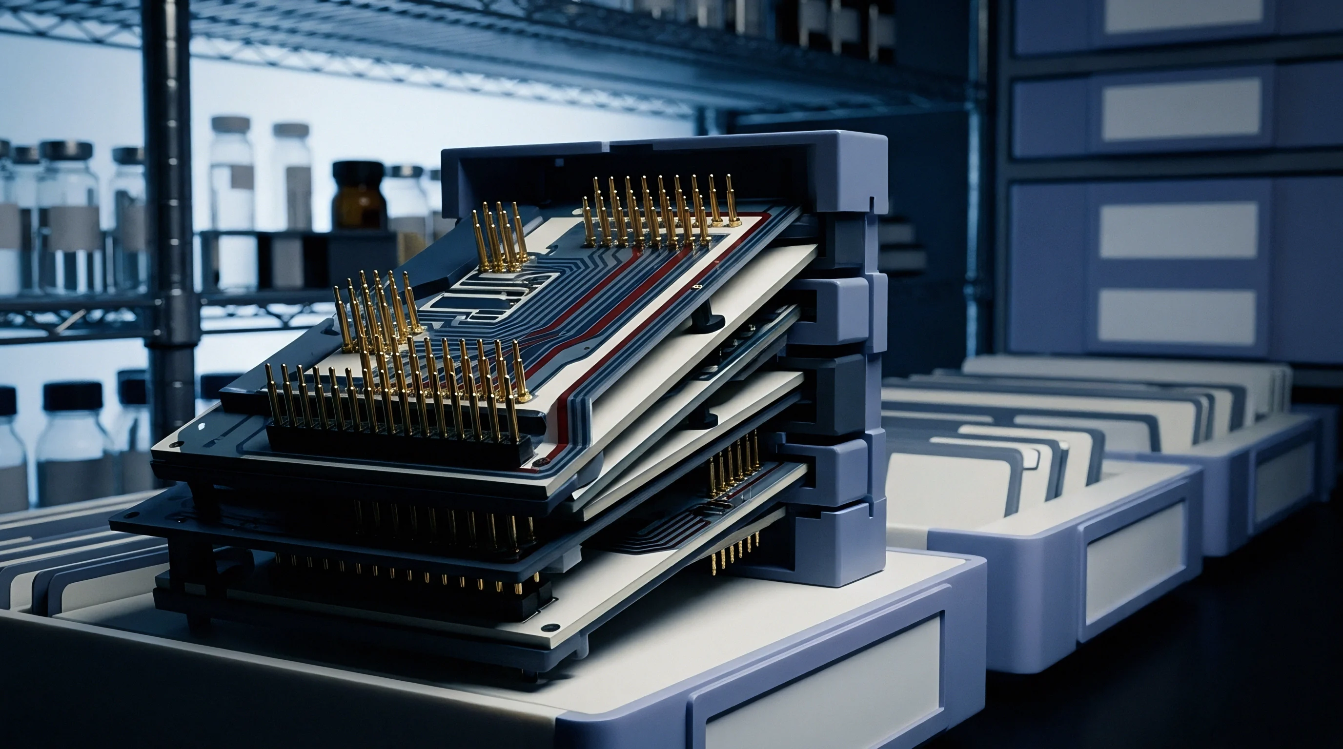
Maintaining mechanical stability during vacuum actuation requires balancing structural support against distributed pneumatic downforce. Bed-of-nails fixtures rely on heavy aluminum or G10 composite top plates, backing plates, and vacuum sealing gaskets for overall rigidity. Any deflection in the top plate transfers directly into the circuit board during engagement, meaning thin tooling plates will flex under continuous vacuum and bow across broad test beds.
Strategic support pin placement directly counters board flexure. Fixed support pins mounted to the fixture base plate extend upward through the probe plates to bear against bare laminate on the board underside, while threaded adjustable pins accommodate local contour variations. Push pins in the fixture lid deliver downward pressure against top-side bare laminate to offset upward probe thrust, while tooling pins maintain board edge alignment and restrict maximum deflection below 100 micrometers under full vacuum.
Distributing support pins evenly opposite spring probe clusters keeps substrate deflection within safe component strain thresholds.
Designing effective support structures follows a structured engineering workflow during fixture construction.
- Map test point coordinates and spring probe force ratings from electrical schematic files.
- Identify high-risk component footprints including ball grid arrays and ceramic chip capacitors.
- Superimpose component keep-out zones over bottom-side test pin locations.
- Select support pin contact positions on open board laminate within 5 millimeters of high-force probe clusters.
- Export final pin placement drill files to fixture fabrication machining software.
Support pin spacing governs unsupported substrate span length. Uniform pin grids work well for evenly distributed test points. High-density probe clusters demand concentrated, customized support layouts to prevent localized substrate deformation.
| Pin Spacing (mm) | Board Thickness (mm) | Peak Deflection (µm) | Max Microstrain | Pass/Fail Status |
|---|---|---|---|---|
| 50 mm Grid | 1.6 mm | 280 µm | 680 microstrain | Fail |
| 30 mm Grid | 1.6 mm | 120 µm | 420 microstrain | Pass |
| 15 mm Grid | 1.6 mm | 45 µm | 180 microstrain | Pass |
| Targeted Cluster | 1.6 mm | 35 µm | 150 microstrain | Pass |
| 50 mm Grid | 1.0 mm | 450 µm | 1120 microstrain | Fail |
| Data measured using three-axis rosette strain gauges at -80 kPa vacuum differential on standard FR-4 assemblies. | ||||
Uniform grid pin spacing is often treated as sufficient to eliminate board bowing, though it bypasses component-specific strain analysis.
Arithmetic
Calculating support pin distribution requires resolving spring probe force vectors against board flexural rigidity. Closed-form mechanical equations treat the circuit assembly as an isotropic plate resting on elastic foundations and discrete pin constraints, where beam flexure dictates that central deflection scales directly with applied load and exponentially with span length.
Static equilibrium across test zones depends on active probe spring forces staying below net atmospheric downforce on every surface increment. If upward spring force from dense probe clusters exceeds downforce, the board unseats from the perimeter vacuum seal and crowns upward.
- Pneumatic Downforce represents total ambient air pressure acting against the evacuated chamber surface area.
- Spring Probe Preload defines initial force exerted by test pins prior to vacuum pull-down.
- Substrate Modulus establishes inherent flexural resistance based on fiberglass weave density and resin type.
- Edge Support Restraint quantifies mechanical clamping resistance along fixture perimeter seals.
Calculating deflection for a uniform square substrate zone bounded by four support pins uses plate bending mechanics equations. Maximum deflection occurs at the geometric center of four surrounding support pins when an upward probe force acts within the span.
Consider a 1.6 millimeter FR-4 test vehicle section with an elastic modulus of 18 gigapascals and a Poisson ratio of 0.14. A cluster of 40 spring probes rated at 2.0 newtons each exerts 80 newtons of upward force over a 20 millimeter by 20 millimeter area. Total vacuum force acting over that same 400 square millimeter region under an 80 kilopascal vacuum equals 32 newtons downward.
Net force acting on this zone equals 48 newtons directed upward. Without local support pins, this net upward thrust causes localized substrate crowning.
| Test Zone | Active Probes | Probe Force (N) | Vacuum Force (N) | Calculated Deflection (µm) |
|---|---|---|---|---|
| Unsupported Center | 40 | 80 N (Up) | 32 N (Down) | 210 µm |
| Standard Grid (35 mm) | 40 | 80 N (Up) | 32 N (Down) | 85 µm |
| High-Density Targeted | 40 | 80 N (Up) | 32 N (Down) | 22 µm |
| Perimeter Zone | 10 | 20 N (Up) | 32 N (Down) | 12 µm |
Positioning support pins directly beneath dense probe clusters balances vacuum pull against probe push across all substrate thickness grades.
Clearance
Physical fixture verification ensures production lots stay within allowable deflection envelopes. Machining tolerances, support pin tip wear, and over-compressed or degraded gaskets introduce dimensional drift over long runs, making periodic fixture audits against original computer-aided design models necessary.
Optical laser displacement sensors verify substrate elevation during active vacuum pull-down. These non-contact measurements track dynamic deflection profiles without introducing physical probe resistance, allowing displacement monitoring above sensitive components throughout production testing where excessive strain would invalidate results.
Laser triangulation measurements during vacuum actuation catch mechanical fixture warping before component solder joints suffer micro-damage.
Fixture release procedures require formal strain measurement qualification reports before signing off on production tools. Accredited test facilities execute baseline strain gauge testing on unpopulated sample circuit boards fitted with rosette sensors across critical components. Fixture qualification dossiers archive measured strain data alongside fixture drill files, spring probe specifications, and maintenance schedule logs.
- Strain Gauge Qualification Report documents peak microstrain levels recorded across all active test points during fixture buy-off.
- Fixture Drill Topography Map verifies precise physical coordinates for spring probes, push pins, and support pins.
- Vacuum Pressure Calibration Log records pressure differential stability and chamber evacuation time constants.
- Maintenance Inspection Sheet tracks probe tip contamination, spring height uniformity, and support pin wear cycles.
Continuous production auditing uses linear differential transducers mounted on the top plate to monitor physical board deflection across every vacuum actuation cycle.