Quantifying Laminate Resin Anisotropy Dispersion and Phase Skew Limits in Gigabit Interconnects
Managing anisotropic permittivity and glass weave dispersion prevents timing jitter and intra-pair phase skew in gigabit differential interconnects.
Tensor
At frequencies above 10 GHz, dielectric substrates in high-speed printed circuits exhibit directional permittivity. Circuit board laminates are composite structures composed of woven glass yarn embedded within a cured polymer matrix. This construction creates a multi-axial permittivity profile where in-plane values differ substantially from values measured through the substrate thickness.
Overlooking this variation leads to inaccurate characteristic impedance calculations, phase velocity mismatches, and unexpected attenuation across high-speed differential channels.

Dielectric Tensor Formulation and Anisotropic Vector Components
Dielectric displacement within reinforced laminates varies along orthogonal axes, requiring a second-rank permittivity tensor aligned with the panel geometry. In a Cartesian coordinate system where the x- and y-axes lie in the laminate plane and the z-axis represents board thickness, the tensor reduces to diagonal form when oriented along the material axes. Continuous glass filaments running in the warp and fill directions govern the in-plane components, epsilon x x and epsilon y y, while the out-of-plane component, epsilon z z, reflects the higher volume fraction of polymer resin between fabric plies.
Woven glass filaments typically exhibit a relative permittivity between 6.0 and 6.8 at microwave frequencies, whereas low-loss resin systems such as polyphenylene ether or fluoropolymers range between 2.1 and 2.8. Consequently, in-plane dielectric constants consistently exceed out-of-plane values. On a high-frequency substrate with a nominal bulk dielectric constant of 3.0, in-plane permittivity generally falls between 3.15 and 3.25, while out-of-plane permittivity spans 2.85 to 2.95.
Heat pressing further aligns functional groups within the polymer matrix, introducing additional directional variation within unreinforced resin zones.
Dielectric constant drops from 3.65 at 1 GHz to 3.38 at 20 GHz when measured using split-cavity resonators at room temperature.
Frequency Dispersion Models and Causality Enforcement
Phase velocity changes across wide signal bandwidths because substrate permittivity and loss tangent vary with frequency. In electromagnetic simulations for signal integrity, the real and imaginary components of the permittivity tensor must satisfy the Kramers-Kronig relations to guarantee physical causality. The wideband Svensson-Djordjevic dispersion model preserves this mathematical causality across gigahertz frequencies using a continuous relaxation spectrum.
The Svensson-Djordjevic dispersion model models the complex permittivity as a logarithmic function bounded by lower and upper transition frequencies, expressed as:
epsilon relative of omega equals epsilon infinity plus delta epsilon divided by natural log of omega high over omega low, multiplied by the natural log of the quantity omega high plus j omega divided by omega low plus j omega.
In this formulation, epsilon infinity represents the asymptotic high-frequency permittivity, delta epsilon defines the dielectric relaxation magnitude, and omega low and omega high represent the bound angular frequencies of the relaxation spectrum, typical set to 1 kHz and 1 THz respectively. Applying this model to anisotropic substrates requires extracting separate wideband parameters for each principal axis of the permittivity tensor, preventing non-causal phase distortion in time-domain interconnect simulations.
Unresolved structural questions persist regarding whether polymer cross-linking orientation asymmetry during multi-cycle lamination processes can be fully decoupled from thermal stress relaxation at high temperatures.

Strand
Woven reinforcement fabrics introduce periodic variations in dielectric constant across the board plane. Mechanical reinforcement fabrics use glass yarn bundles woven in perpendicular warp and fill directions. The pitch between adjacent bundles creates an alternating grid of dense glass intersections and resin-rich windows beneath surface and internal conductors.
Glass Fabric Style Architecture and Bundle Pitch
Conventional glass styles such as 106 and 1080 bundle filaments tightly into dense cylindrical yarns, leaving open resin windows between adjacent strands. Conductors traversing these patterns experience periodic shifts in effective permittivity. Spread glass styles, including 1035, 1078, and 3313, undergo mechanical un-twisting during yarn production to flatten the glass filaments into broad, uniform ribbons that close open resin windows and smooth the local dielectric profile.
Substrate thickness variations occur during pressing as resin flows into the open windows of standard glass weaves. The resulting local resin content fluctuations generate spatial permittivity shifts up to 0.35 dielectric constant units between adjacent trace positions. Spread fabrics substantially reduce this spatial variance to less than 0.05 units, drastically narrowing the phase velocity distribution experienced by high-speed differential signal pairs.
Compliance with IPC-4101 specification sheets obligates material coaters to publish nominal dielectric loss tangent tolerances across all production master rolls.

Resin Flow Dynamics and Microstructural Phase Distribution
During multilayer lamination, hydraulic pressure forces liquefied resin into the voids between glass filaments while temperature ramps govern viscosity. As the thermosetting resin softens and flows past solid filaments, local shear stresses orient long-chain molecules parallel to fiber surfaces, forming a boundary layer whose dielectric properties diverge from the bulk resin.
Uncontrolled resin displacement introduces structural anomalies that degrade signal transmission reliability across high-speed channels:
- Micro-cavity formation creates localized air pockets within resin-rich windows, dropping local dielectric permittivity to near 1.0 and shifting channel impedance unpredictably.
- Fiber bundle displacement alters the mechanical symmetry of the inner-layer core, inducing localized phase skew between differential trace routing paths.
- Resin depletion zones emerge near high-density copper features, reducing overall substrate thickness and elevating out-of-plane electric field concentration.
- Polymer phase separation generates localized density variations in blended resin systems, creating small-scale dielectric dispersion anomalies at high frequencies.
The table below presents physical glass bundle parameters and directional permittivity variations across common reinforcement styles:
| Weave Style | Glass Yarn Construction | Nominal Resin Content (%) | Pressed Thickness (mm) | Out-of-Plane Dk (z-axis at 10 GHz) | In-Plane Dk (xy-axes at 10 GHz) |
|---|---|---|---|---|---|
| 106 Standard | Single Yarn Loose | 68 | 0.033 | 2.72 | 3.05 |
| 1080 Standard | Single Yarn Standard | 62 | 0.071 | 2.95 | 3.32 |
| 1035 Spread | Un-twisted Spread Ribbon | 65 | 0.028 | 2.80 | 3.08 |
| 1078 Spread | Un-twisted Spread Ribbon | 64 | 0.043 | 2.88 | 3.16 |
| 3313 Spread | Heavy Spread Filament | 55 | 0.081 | 3.12 | 3.45 |
Minor glass fiber bundle movement during hydraulic hot pressing generally falls within published baseline statistical limits.


Phase
Differential interconnects running at 56 Gbps and 112 Gbps PAM4 require strict electrical symmetry between conductors. Intra-pair skew ~ the difference in propagation delay between the positive and negative lines ~ converts differential energy into common-mode noise whenever local glass density or material anisotropy diverges, degrading eye height and consuming timing margins.

How Do Material Tolerances Impact Timing Budgets?
When conductors in a pair encounter unequal amounts of glass, their propagation velocities diverge. The phase velocity v_p of a signal propagating along a transmission line depends directly on the effective dielectric constant epsilon_eff of the surrounding material, defined by the formula:
v p equals c divided by square root of epsilon eff
In this equation, c represents the speed of light in a vacuum. When one conductor of a differential pair sits directly over a glass bundle while the twin conductor sits over a resin-rich window, the two conductors experience different effective dielectric constants. The resulting phase delay imbalance delta t over a physical routing distance L is expressed quantitatively as:
delta t equals L divided by c, multiplied by the quantity square root of epsilon eff 1 minus square root of epsilon eff 2.
At 112 Gbps PAM4 signaling rates, the total unit interval UI corresponds to approximately 17.8 picoseconds. System timing budgets restrict intra-pair phase skew to less than 5 percent of the unit interval, establishing a strict upper limit of approximately 0.89 picoseconds total allowable skew across the entire physical channel path.
Wider trace pitch on spread glass substrates dampens differential timing skew caused by localized resin volume variations.
Intra-Pair Skew Calculation and Interconnect Skew Budgeting
Quantitative timing analysis evaluates differential signal skew accumulation over total path length. Consider a worked engineering calculation evaluating a 112 Gbps PAM4 channel routed across a 300 mm trace length on a high-speed substrate. The stackup design specifies a nominal out-of-plane dielectric constant of 3.00, but spatial resin orientation variation introduces an effective dielectric constant difference of 0.06 between the two legs of the differential pair (epsilon_eff1 = 3.03, epsilon_eff2 = 2.97).
Calculating the propagation delays across the 300 mm channel length:
t 1 equals 0.300 divided by 3.00 times 10 to the 8th power, multiplied by square root of 3.03, yielding 1.7407 nanoseconds.
t 2 equals 0.300 divided by 3.00 times 10 to the 8th power, multiplied by square root of 2.97, yielding 1.7234 nanoseconds.
The resulting timing skew delta t equals t 1 minus t 2, which equals 17.3 picoseconds. This accumulated skew exceeds the allowable intra-pair skew budget of 0.89 picoseconds by nearly twenty times, completely closing the PAM4 reception eye diagram at the receiver IC input. To mitigate this catastrophic skew accumulation, differential pair traces must be routed at a calculated offset angle relative to the substrate weave orientation, or specified exclusively on ultra-flat spread glass substrates.
Ignoring dielectric anisotropy dispersion during stackup design leads to total timing closure failure on long-reach backplane interconnects, resulting in scrapped production lots and missed commercial delivery schedules.

Bench
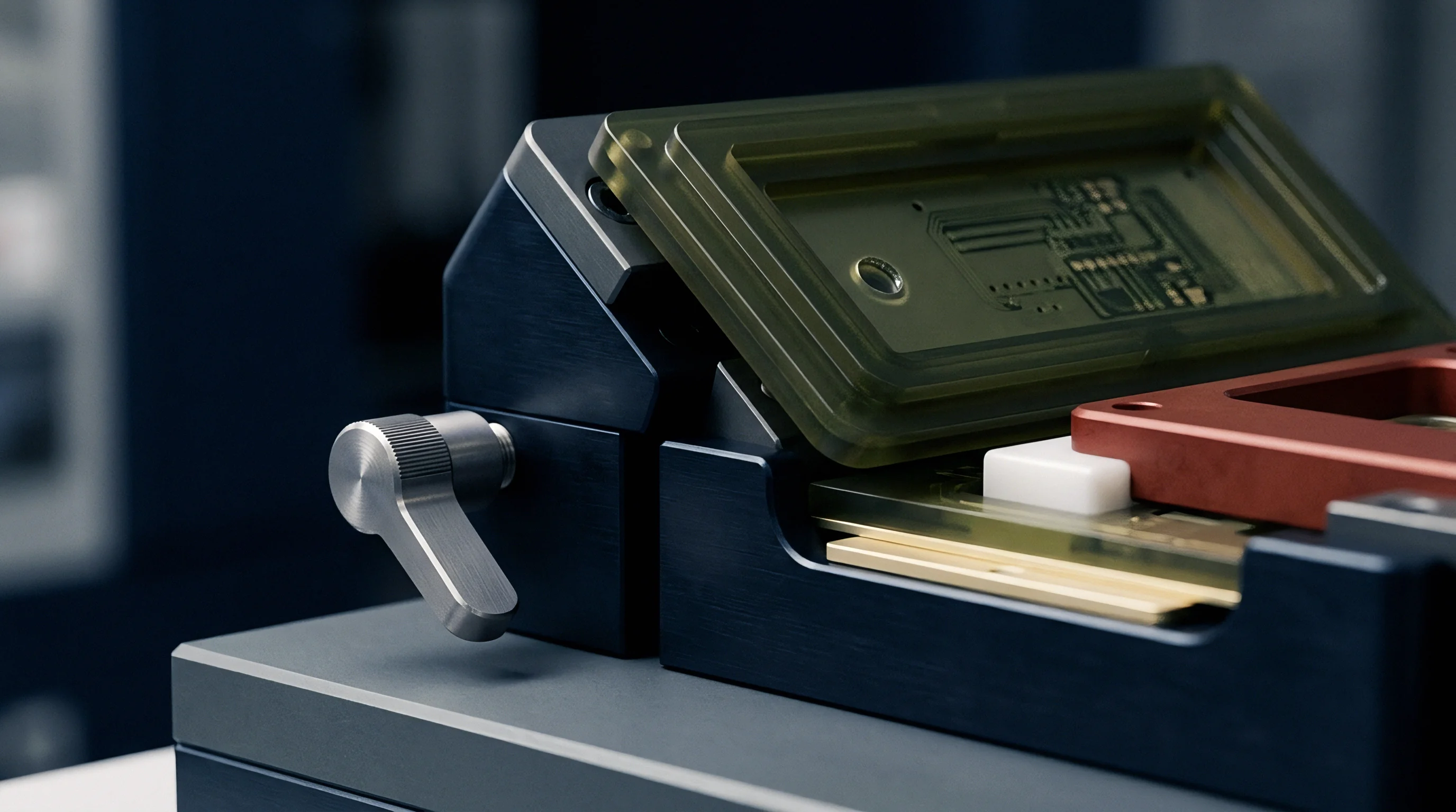
Accurate measurement of substrate anisotropy requires specialized RF test fixtures. Standard flat-plate capacitance methods measure dielectric parameters purely in the out-of-plane direction at low frequencies, missing in-plane properties and high-frequency dispersion entirely. Precision microwave metrology relies on resonant cavities and time-domain fixtures to extract the full diagonal dielectric tensor.

Resonator Methods for Out-of-Plane Characterization
Extracting dielectric properties perpendicular to laminate surfaces demands cavity structures operating in distinct electromagnetic modes. Split Cylinder Resonators, operating per IPC-TM-650 Method 2.5.5.13, utilize TE011 resonance modes to measure out-of-plane permittivity and loss tangent without requiring metal plating applied directly to test samples. The test sample is inserted between two cylindrical cavity halves, and the resonant frequency shift and quality factor Q-factor change are measured using a High-Frequency Vector Network Analyzer.
Balanced Circular Disk Resonators provide accurate dielectric measurements for clad substrate materials. By establishing circular cavity resonance between two parallel copper layers, this method extracts out-of-plane properties across discrete harmonic frequencies up to 40 GHz. Thermal variations during testing expose the temperature coefficient of dielectric permittivity, revealing how thermal expansion shifts substrate electrical behavior.
Phase skew accumulation scales linearly with physical channel length on un-rotated differential interconnects.

In-Plane Extraction Techniques and Broadband Fixtures
Parallel line structures etched on test panels permit determination of parallel dielectric constants across broad frequency bands. Split Post Dielectric Resonators utilize TE01delta modes to generate electromagnetic fields parallel to the substrate surface, isolating the in-plane permittivity tensor components epsilon xx and epsilon yy. Combining split cylinder measurements with split post measurements resolves the full dielectric anisotropy matrix of raw unclad laminates.
The following sequence details the operational laboratory procedure for extracting anisotropic dielectric tensor parameters from raw substrate coupons:
- Prepare a flat 50 mm by 50 mm substrate coupon, ensuring edges are cut clean and free of micro-burrs.
- Bake the test coupon at 105 degrees Celsius for 120 minutes to eliminate absorbed moisture prior to measurement.
- Position the unclad coupon within the Split Post Dielectric Resonator cavity to measure in-plane permittivity component epsilon xx and in-plane loss tangent tan delta xx.
- Transfer the coupon to the Split Cylinder Resonator cavity operating in TE011 mode to measure out-of-plane permittivity component epsilon zz.
- Record resonant frequency spectra from 1 GHz to 40 GHz using a calibrated Vector Network Analyzer.
- Calculate the dielectric anisotropy ratio by dividing in-plane permittivity epsilon xx by out-of-plane permittivity epsilon zz.
To eliminate timing budget failures across high-speed channels, engineering specifications must define dielectric parameters using standard test fixtures. The table below compares primary test techniques used for anisotropic dielectric qualification:
| Test Method Standard | Test Fixture Type | Frequency Range (GHz) | Target Permittivity Tensor Component | Typical Measurement Precision |
|---|---|---|---|---|
| IPC-TM-650 2.5.5.5 | Clamped Stripline Line | 1 to 10 | Out-of-Plane (epsilon zz) | plus minus 2.0 percent |
| IPC-TM-650 2.5.5.13 | Split Cylinder Resonator | 10 to 30 | Out-of-Plane (epsilon zz) | plus minus 0.5 percent |
| ASTM D2520 | Balanced Circular Disk | 1 to 40 | Out-of-Plane (epsilon zz) | plus minus 1.0 percent |
| IEC 61189-2-721 | Split Post Resonator | 1 to 20 | In-Plane (epsilon xx, yy) | plus minus 0.8 percent |
| IEEE 370 Annex E | TDT Phase Extraction | 1 to 50 | Effective In-Circuit (epsilon eff) | plus minus 1.2 percent |
| Precision figures represent typical laboratory measurement tolerances achieved when controlling environmental temperature to 23 degrees Celsius plus minus 1 degree and relative humidity below 50 percent. | ||||
Fabrication notes specifying IPC-4101 slash sheet compliance require material suppliers to verify out-of-plane dielectric constants using split cylinder resonator testing before releasing laminate lots for multi-layer press cycles.
Spec
Procurement documents for high-frequency circuit boards govern acceptable material substitution rules and stackup manufacturing tolerances. Standard slash sheet calls out often group laminates by general resin chemistry, neglecting directional anisotropy variations and glass weave geometry. Purchasing bare panels based on broad dielectric classifications without specifying physical weave styles invites severe intra-pair skew defects and impedance variation in finished products.
Procurement Control Notes and Array Layout Constraints
Engineering release packages for gigabit interconnect products must lock down physical stackup parameters through explicitly stated fabrication notes. Stackup drawings must specify exact laminate manufacturer part numbers, resin content percentages, copper foil surface treatment profiles, and glass fabric style numbers for every dielectric core and prepreg layer. Array panelization plans must mandate specific board placement orientation relative to panel master roll direction, preventing unintentional phase skew variations caused by panel rotation during fabrication steps.
Panel layout guidelines must enforce zig-zag or angled routing profiles for long differential pairs when standard glass fabrics are used. Alternatively, specifying mechanically spread glass fabrics across all high-speed signal layers permits standard orthogonal trace routing without incurring intra-pair skew penalties, maximizing panel area utilization and reducing trace routing complexity.
Commercial Laminate Sourcing and Yield Optimization
Substrate selection directly drives overall PCB panel costs, manufacturing yields, and delivered board prices. Upgrading from standard glass weave FR-4 to low-loss polyphenylene ether laminates with spread glass fabric introduces a raw material cost step of approximately 2.5 to 3.5 times per panel area. However, choosing cheaper standard weave substrates introduces high skew failure risks in production testing, driving manufacturing yields down and increasing total landed unit costs.
The matrix below maps commercial substrate material grades against cost factors, yield impacts, and recommended routing constraints:
| Material Grade | Resin System Type | Relative Panel Cost Multiplier | Skew Control Yield Penalty | Recommended Differential Routing Angle |
|---|---|---|---|---|
| Standard High-Tg FR-4 | Epoxy Silane Blend | 1.0x | High (30 to 50 percent drop) | 10 to 15 Degree Angled Off-Axis |
| Mid-Loss Speed Grade | Modified Epoxy PPE | 1.8x | Moderate (10 to 20 percent drop) | 5 to 10 Degree Angled Off-Axis |
| Low-Loss High-Speed | Polyphenylene Ether (PPE/PPO) | 2.8x | Low (below 3 percent drop) | Orthogonal on Spread Glass |
| Ultra-Low Loss Hydrocarbon | Thermoset Hydrocarbon | 4.2x | Negligible (below 1 percent drop) | Orthogonal on Spread Glass |
| Fluoropolymer Matrix | PTFE Composite | 6.5x | Negligible (below 1 percent drop) | Orthogonal Standard Routing |
Specifying spread glass weave materials on all inner signal layers yields predictable phase timing compliance without requiring complex off-axis routing angles on production master panels.