Thermal Cycling Screen Calibration for Multi Layer ASIC Interconnect Defect Isolation
Calibrating ASIC thermal cycling requires matching ramp rates and dwell times to die-level thermal lag, isolating latent microvia defects without exceeding fatigue limits.
Warp
Thermal Expansion Mismatch across Substrate Interfaces
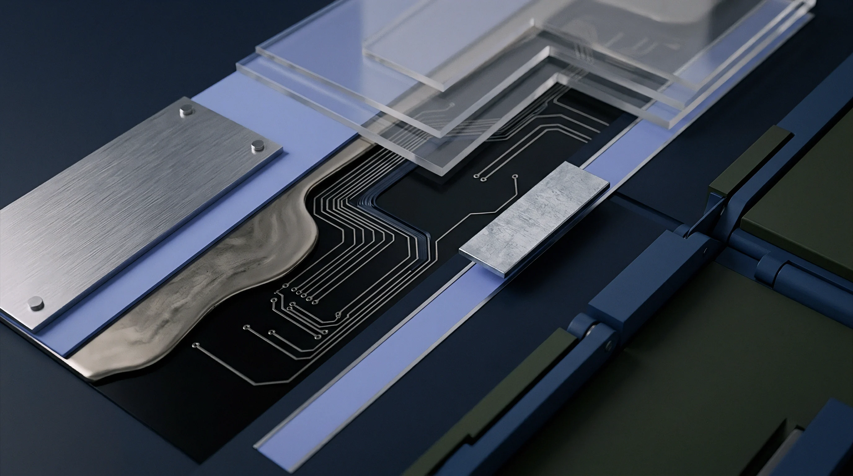
Differential thermal expansion inside a multi-layer application-specific integrated circuit (ASIC) generates severe mechanical strain across internal interconnects. Silicon dies have a coefficient of thermal expansion near 2.6 parts per million per degree Celsius, while organic substrate materials expand at 12 to 15 parts per million per degree Celsius. Copper interconnect traces, through-silicon vias, and microvias sit locked between these opposing dimensional shifts.
Rapid temperature swings force adjacent materials to expand and contract at unequal rates: microvia barrels stretch, target pads shear, and controlled collapse chip connection (C4) solder bumps absorb cyclic displacement. Without precise stress screening, units with marginal microvia plated copper or latent delamination easily pass initial continuity checks, failing only after deployment in high-reliability field hardware.
Interconnect integrity degrades through cumulative microstructural fatigue. Plated copper inside multi-layer redistribution layers (RDL) experiences peak tensile force at the high-temperature peak of a thermal cycle, where vertical expansion of the substrate resin matrix pulls microvia barrels away from internal capture pads. If electrodeposition leaves uneven copper wall thickness or grain boundary voids, stress concentrates at those thin regions, converting small flaws into propagating cracks under repeated flexing.
Standard continuity testing at static room temperature misses these defects entirely ~ the thermal expansion that opens a crack at high temperatures recedes as the board cools, restoring contact and masking the flaw during bench inspection.
Unscreened microvia barrel cracks reclose during ambient room temperature electrical testing.

Dominant Failure Modes in Multi-Layer Interconnects
Screening programs focus on isolating four distinct physical failures before assembly integration:
- Microvia barrel cracking occurs when z-axis thermal expansion of the dielectric substrate exceeds the tensile yield strength of electrodeposited copper plating, fracturing the via wall.
- Target pad separation develops when shear stress at the interface between the microvia base and the underlying capture pad overcomes the metallurgical bond, creating a strain-sensitive open circuit.
- C4 solder bump fatigue manifests as crack propagation through the intermetallic compound layer under cyclic thermal warping between the silicon die and organic package.
- Inter-layer dielectric delamination originates from interface adhesion loss triggered by thermomechanical shear along copper-resin boundaries during rapid temperature transitions.
Using an uncalibrated thermal cycling profile leads either to missed field failures or to unnecessary fatigue in sound components. Overly steep ramp rates introduce transient stresses that damage good interconnects, while brief dwell times prevent package cores from reaching thermal equilibrium. The financial penalty for an undetected interconnect flaw rises roughly tenfold at each assembly stage: a latent microvia failure caught at package test costs pennies, but the same defect identified after board population or system delivery ruins assembly yields and triggers expensive field replacements.
Ramp
Profile Parameterization and Thermal Lag Dynamics
Calibrating a thermal cycling stress screen requires a balance between profile ramp rate, peak dwell duration, and extreme temperature limits. Transition rates measured in chamber air rarely reflect what internal ASIC interconnects experience, because package thermal mass creates substantial lag between ambient air and internal silicon junctions. Thermocouples embedded inside sacrificial package samples show that core temperatures trail air transitions by several minutes.
If the chamber shifts immediately into a soak phase before the internal die reaches thermal equilibrium, effective stress duration falls below specification.
Ramp rates between 10 and 15 degrees Celsius per minute accelerate thermomechanical strain without introducing non-representative shock mechanisms. Rates exceeding 20 degrees Celsius per minute generate steep spatial temperature gradients across the package substrate, causing uneven die warping that distorts failure isolation data. Solder joint stress relies on both total temperature range and creep time during the dwell phase.
High-temperature dwell periods allow solder alloys to relax through plastic deformation, whereas low-temperature dwells freeze the strain in place. Dwell times must last long enough for the package center to remain at minimum and maximum thermal targets for at least five minutes.
A package core temperature trails chamber air transition by up to four minutes during a fifteen degree per minute ramp.
Thermal Profile Calibration Procedure
Establishing an effective thermal cycling screen requires empirical temperature mapping using dedicated test hardware:
- Instrument a non-functional ASIC package with calibrated micro-thermocouples embedded at the center die surface, corner C4 bumps, and external substrate edge.
- Mount the instrumented package onto a representative circuit board located in the center of the thermal test chamber load matrix.
- Execute a baseline thermal profile cycling from minus forty to plus one hundred twenty-five degrees Celsius at a nominal ramp rate of ten degrees per minute.
- Measure the thermal lag time between ambient air sensors and the internal package die thermocouple during heating and cooling transitions.
- Adjust profile soak durations to guarantee that the internal die maintains target extreme temperatures for a minimum of ten continuous minutes per cycle.
- Verify that the spatial temperature gradient across adjacent package substrate corners remains below five degrees Celsius during peak ramp rates.
Thermal profiles must conform to standardized test conditions defined in industry specifications to ensure repeatable defect activation without altering fundamental failure physics.
| Parameter | JESD22-A104 Condition G | IPC-9701 Preference Profile | Calibrated Screen Profile |
|---|---|---|---|
| Data derived from standardized environmental stress testing protocols applied to flip-chip BGA packages. | |||
Standard factory continuity testing is often assumed to catch all interconnect defects and avoid consuming package life through environmental screening. Physical cross-sections of returned field units disprove this assertion, showing microvia necking that opened exclusively under thermal load.

Rig

Can Continuous Resistance Monitoring Isolate Microvia Delamination during Ramp Phase?
Detecting intermittent microvia opens requires continuous electrical monitoring during thermal transitions. Static continuity checks conducted after cycling fail to reveal latent interconnect flaws. As chamber temperature rises, dielectric thermal expansion opens tiny separations in cracked microvia barrels or target pads.
When the temperature returns to ambient, the substrate contracts, pressing the fractured metal interfaces back together. Standard bench meters show full continuity on these cooled units. Continuous high-speed monitoring records transient resistance spikes occurring over millisecond windows during active temperature ramps.
In-situ monitoring relies on high-density four-wire Kelvin sensing or active boundary scan polling chains. Micro-ohm resistance shifts signal the early stages of microvia separation long before complete open-circuit failure occurs. Data acquisition systems must sample sensing channels at high frequencies to catch short-duration high-resistance events.
Connecting internal test structures in daisy-chain configurations allows efficient monitoring of thousands of substrate vias and C4 bumps across a single channel, where high-frequency glitch detection circuits trigger flags whenever resistance exceeds nominal thresholds.
| Monitoring Method | Resistance Resolution | Sampling Frequency | Defect Isolation Capability |
|---|---|---|---|
Configuring in-situ telemetry systems requires selecting the appropriate sensing architecture based on package pin access and defect isolation objectives:
- Dedicated Kelvin daisy-chain arrays isolate microvia and solder joint net groups by eliminating socket and lead resistance from the measurement path.
- Active boundary scan loop testing polls internal ASIC logic blocks continuously during thermal transitions to identify dynamic trace logic failures.
- High-speed signal integrity monitoring tracks RF reflection coefficients along critical interconnect lines to locate impedance variations caused by sub-micron cracking.
Because transient glitches vanish under static probe inspection, real-time telemetry during temperature ramping provides the only definitive proof of structural interconnect integrity under stress.
Margin

Fatigue Accumulation and Life Consumption Models
Calibrating a thermal cycling screen requires precise accounting of package fatigue life consumption. Every cycle uses up part of the interconnect’s total plastic deformation budget. The Coffin-Manson relation models thermomechanical fatigue life by linking cyclic plastic strain range to cycles to failure.
Over-screening an ASIC batch consumes fatigue margin that should remain for field operation, while under-screening leaves latent defects active. Proper calibration establishes the minimum cycle count required to precipitate latent flaws into measurable opens without exceeding five percent of the product’s total operational life expectancy.
The Norris-Landzberg modification incorporates cycling frequency and peak temperature factors into the basic Coffin-Manson equation. Calculating the acceleration factor allows test engineers to map screening chamber profiles to real-world operating conditions. Plastic strain range dominates low-cycle fatigue accumulation in solder bumps and copper interconnects.
Determining the damage fraction per screen cycle allows engineers to adjust screening duration to target latent defect populations precisely.
The acceleration factor formula models the strain-life relationships across operating environments:
AF = ( Delta T_test / Delta T_use )^m ( f_use / f_test )^n exp( ( E_a / k ) ( 1 / T_max_use – 1 / T_max_test ) )
In this relationship, Delta T represents the thermal cycle temperature range, f represents the cycling frequency, E_a represents the activation energy for solder creep or copper work hardening, k represents the Boltzmann constant, and T_max represents the absolute maximum temperature in Kelvin. The exponents m and n account for strain range and frequency dependencies based on material alloy selection.
| Screening Parameter | Aggressive Screen | Calibrated Screen | Conservative Screen |
|---|---|---|---|
Quantifying screening parameters requires balancing strain rate against fatigue consumption across four primary variables:
- Thermal cycle temperature range sets the ultimate strain displacement imposed across silicon-substrate boundaries during each cycle.
- Dwell time duration governs the degree of stress relaxation and plastic creep deformation occurring within solder joints at temperature extremes.
- Cycle transition frequency influences the strain rate applied to microvia barrel electrodeposition plating structures.
- Package material creep exponent determines how rapidly thermal strain converts to permanent microstructural damage inside metal interconnects.
IPC-9701 Clause 4.2 dictates that qualification screening must not consume more than five percent of total package fatigue life before deployment.
How much fatigue damage can a specific multi-layer redistribution layer absorb during screening before microvia barrel work-hardening initiates micro-cracking in healthy copper crystal grains?


Filing

Technical File Evidence and Acceptance Criteria
Demonstrating compliance with customer product specifications requires formal test file documentation. A valid screening report records real-time resistance telemetry logs, thermal chamber profile verification records, and statistical lot yield analysis. Unsubstantiated supplier certificates claiming compliance with general thermal standards do not constitute proof of defect isolation.
The technical dossier must contain raw temperature log data demonstrating that internal die temperatures reached required dwell targets during every cycle. Any transient resistance anomaly recorded during cycling triggers mandatory lot disposition procedures.
Lot acceptance conditions rely on statistical threshold limits set for first-pass screening yield. If screening failures in a manufacturing batch exceed two percent of total submitted units, the entire lot enters quarantine for failure analysis. High failure rates indicate a systemic fabrication process shift rather than isolated workmanship defects.
Microsection analysis of failed units isolates the failure location to specific interconnect layers, identifying whether the flaw originated in wafer-level processing, substrate fabrication, or package assembly.
Real-time resistance logs and internal die thermocouple data form the core evidence required for batch shipment authorization.
Test reports must include specific calibration metrics, chamber loading maps, and failure isolation data to satisfy quality audit requirements. Guard-banding thermal limits protects against chamber spatial variations and calibration drift during long production runs. Sourcing contracts specifying thermal cycling requirements must mandate continuous in-situ resistance monitoring rather than post-test continuity sampling.
Incorporating explicit screening parameters into procurement specifications prevents suppliers from substituting cheap static soak tests for calibrated stress screens, ensuring that delivered ASICs survive their full intended operating lifespan.
JESD22-A104 Clause 5.1 defines mandatory lot re-qualification triggers when substrate supplier processes change resin formulations or microvia plating chemistries.