Modeling Hydrodynamic Resin Squeeze-Out Shear Mechanics and Tensorial Permittivity Drift in Multi-Pass Sequential Lamination Buildup Substrates
Resin squeeze-out shear distorts dielectric tensor components and drives microvia misregistration in multi-pass buildup substrates.
Rheology
Hydrodynamic Squeeze Flow Dynamics
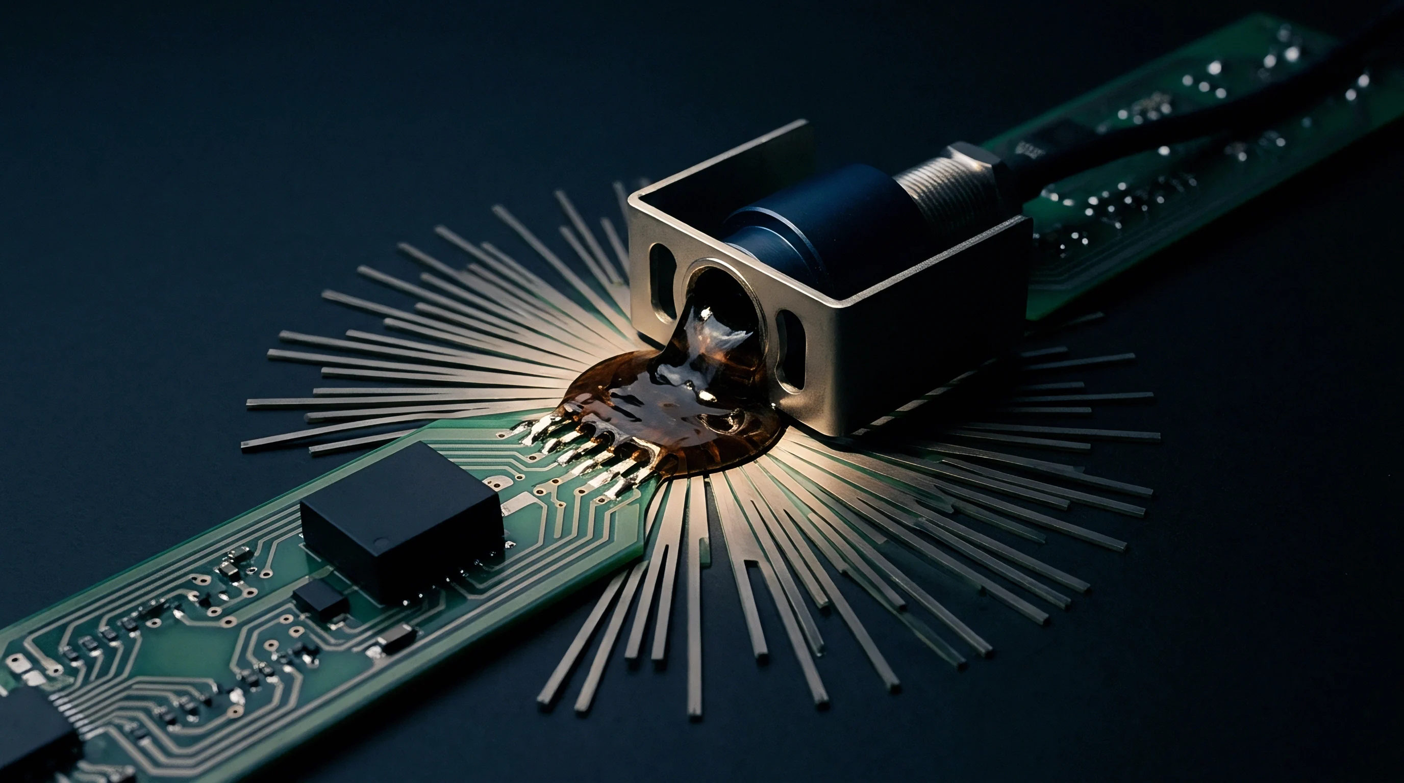
During sequential lamination, elevated temperatures and uneven transient pressure act on uncured or semi-cured B-stage prepregs and dielectric buildup films. As squeeze-out begins, the polymer matrix passes through its minimum melt viscosity window prior to gelation. Thin-film Navier-Stokes equations show that velocity gradients across the dielectric gap create high shear stress along inner-layer copper boundaries.
These pressure gradients push resin laterally from dense pattern regions toward areas with less copper, skewing the local resin-to-glass ratio across the panel.
Mechanical press force balances against the viscous drag of the molten resin during hot lamination. High squeeze rates concentrate shear strain around the copper foil teeth, causing unreinforced resin channels to thin unevenly. That variation alters target dielectric spacing between adjacent signal lines, producing impedance shifts that scale directly with regional differences in feature density.
Peak hydrostatic pressure during resin minimum melt viscosity dictates the final bond-line thickness across micro-cavities.
In multi-pass buildup stacks, each thermal cycle re-softens underlying dielectric layers to an extent set by their glass transition temperature and cure state. Cumulative shear at these lower dielectric interfaces introduces micro-distortions into embedded traces, shifting baseline dimensions. Fabricators manage this flow window by tuning heating ramp rates between 1.5 and 3.0 degrees Celsius per minute.
Viscoelastic Shear Mechanics at Metal Interfaces
High shear near the copper interface aligns polymer chains locally, shifting the resin’s mechanical response from isotropic to orthotropic. The severity of this interfacial shear depends on the copper foil profile, where surface depth and tooth density act as mechanical anchors resisting lateral squeeze-out.
High-profile electrodeposited foils slow fluid movement at the interface, forming a stationary boundary layer that focuses shear strain in the bulk resin a set distance from the metal. Reverse-treated and ultra-low-profile foils reduce this anchoring effect, allowing more resin slip and redistributing shear strain. Unbalanced copper layouts accentuate these velocity gradients, warping internal layer pairs on a micro scale.
| Temperature Ramp Rate (°C/min) | Minimum Viscosity (Pa·s) | Flow Window Duration (s) | Peak Shear Stress (kPa) | Lateral Squeeze Velocity (mm/s) |
|---|---|---|---|---|
| 1.5 | 45 | 420 | 12.4 | 0.08 |
| 2.0 | 32 | 310 | 18.7 | 0.14 |
| 2.5 | 21 | 225 | 26.3 | 0.22 |
| 3.0 | 14 | 160 | 35.8 | 0.31 |
Modulating press force during minimum viscosity controls core movement. Mechanical stops or displacement-controlled hydraulic presses prevent excessive resin starvation over high-relief copper. Because low-loss epoxy and polyphenylene ether resins are sensitive to strain rates, press profiles must be tightly set to fill microvia voids without over-thinning peripheral dielectric zones.
Using high-flow prepregs with extended gel times can fill pattern voids, but excess squeeze-out compromises outer-layer registration by shifting core positions relative to the drill target reference frame.
Permittivity
Tensorial Permittivity Drift Mechanics
Dielectric anisotropy develops when polymer chains and glass fibers undergo permanent deformation during multi-pass lamination. Permittivity is modeled as a second-rank tensor with separate in-plane and out-of-plane components. Shear forces during squeeze-out shift the orientation of polar functional groups in the resin matrix, driving divergence between in-plane and out-of-plane values.
Glass weave distortion compounds tensorial drift under heavy press loads.Rapid resin flow across glass fabric pulls and displaces individual yarn bundles. This local compression alters the volume ratio of E-glass or L-glass to resin along signal paths, shifting local tensor components away from nominal bulk values.
Anisotropic dielectric tensor components diverge significantly when localized shear strain exceeds five percent in woven glass substrates.
This drift accumulates with each lamination pass in sequential HDI builds. Cores run through three or four press cycles show out-of-plane z-axis permittivity shifts up to four percent. High-frequency inner-layer traces then experience phase velocity fluctuations along their path due to these directional variations.
High-Frequency Impedance and Phase Distortion
Impedance calculations based on isotropic permittivity introduce systematic errors in sub-terahertz and millimeter-wave designs. Differential pairs passing through uneven squeeze-out regions develop phase skew, mode conversion, and localized reflections. Modeling wave propagation through these anisotropic channels requires split-tensor calculations with explicit axial permittivity values at each coordinate.
Fabrication notes often overlook tensorial shifts, listing only single-point permittivity measured at 1 kHz or 1 MHz using capacitive methods. Testing at 10 GHz with split-post dielectric resonators or balanced striplines reveals the full anisotropy created during lamination.
- Anisotropic Tensor Asymmetry alters field distribution in coplanar waveguides, causing localized impedance dips across dense copper fill zones.
- Z-Axis Dielectric Thru Drift degrades phase velocity uniformity across multi-layer high-speed bus interfaces, worsening eye pattern symmetry.
- Fiber Bundle Compression alters local capacitance along trace runs, introducing periodic reflections matched to the glass fabric pitch.
- Thermal-Mechanical Pre-Strain permanently skews directional loss tangent values, increasing attenuation over long transmission lines.
Measuring tensorial components requires microstrip ring resonator test coupons oriented at zero, forty-five, and ninety degrees to the warp weave. Resonance frequency splits from these coupons provide the values needed to populate off-diagonal tensor terms.
Standard laminate procurement specifications state permittivity tolerances under static IPC-TM-650 test conditions, leaving fabrication-induced drift outside vendor liability.
Distortion
Multi-Pass Thermal Degradation and Core Alignment
Each lamination cycle subjects the core to thermal excursions up to or above 220 degrees Celsius. These thermal spikes advance residual cure, increase cross-link density, and raise the glass transition temperature of early dielectric layers. At the same time, repeated press clamping leaves residual strain memory in inner-layer copper patterns.
Core distortion appears as micron-scale shifts across large panels. Uneven stress between dense routing fields and open copper voids causes non-linear expansion, complicating drill-to-layer registration for microvias in outer buildup passes.
| Build Pass Index | Substrate Base Material | Mean Misregistration (µm) | Z-Axis Permittivity Shift (%) | Yield Retained (%) |
|---|---|---|---|---|
| Pass 1 (Core) | High-Tg FR-4 | 12.1 | +0.2 | 99.4 |
| Pass 2 (Buildup 1) | Hydrocarbon/Glass | 24.8 | +1.1 | 96.8 |
| Pass 3 (Buildup 2) | Unreinforced Resin Film | 39.5 | +2.6 | 91.2 |
| Pass 4 (Buildup 3) | Unreinforced Resin Film | 57.2 | +4.1 | 82.5 |
Fabricators apply dynamic scaling during laser direct imaging to maintain hole-to-pad alignment. While these scale factors correct for predicted linear expansion or contraction from batch records, they do not capture localized, non-linear distortion caused by hydrodynamic resin shear.
Non-linear core distortion scales directly with the asymmetry of inner-layer copper weight distribution across working panels.
When registration errors exceed pad margins, annular ring breakout occurs. This reduces long-term reliability and encourages conductive anodic filament growth along stress micro-fissures.
Modeling Hydrodynamic Squeeze-Out Shear Mechanics
Predicting spatial resin flow requires coupled fluid-structure interaction modeling. Finite element models must account for temperature-dependent viscosity, non-Newtonian shear-thinning, and flow through glass fiber meshes as a porous medium. Trace movement and tilt are only captured when structural copper response is tied directly to fluid pressure fields.
Incorporating these mechanics into yield models lets stackup designers balance dielectric thicknesses before generating tool paths. Aligning prepreg gel timing with layer topography prevents local resin starvation and contains tensorial permittivity drift along high-speed channels.
- Run micro-cavity flow simulations using empirical viscosity profiles to locate high-shear zones across complex signal layers.
- Adjust copper thieving patterns in open areas to balance fluid pressure fields and equalize lateral resin displacement rates.
- Apply asymmetric scaling factors to laser imaging files based on coupled thermal-mechanical shear displacement predictions.
- Validate dielectric tensor stability using high-frequency stripline test coupons embedded within panel scrap borders.
Process yields drop sharply once cumulative registration errors cause automated optical inspection to reject microvia targets.
Tight registration tolerances on pass four can only be sustained by dropping working panel utilization from six boards per panel down to four to reduce edge-effect distortion.

Economics
Panel Yield and Landed Cost Mechanics
Material selection and lamination pass count determine panel utilization and unit board cost. Ultra-low-loss laminates built for sub-terahertz work carry steep price premiums over standard high-Tg substrates. Compounded by yield losses from multi-pass registration drift, unit costs rise quickly.
Tooling, press energy, and extended cycle times add up quickly in production. A four-pass sequential buildup occupies far more press time and inspection capacity than a single-pass HDI board, reducing plant throughput and extending lead times.
| Stackup Architecture | Lamination Passes | Raw Material Cost Ratio | Process Cost per Panel ($) | Estimated Final Yield (%) |
|---|---|---|---|---|
| Standard 10-Layer HDI | 1 | 1.0 | 145.00 | 94.5 |
| Sequential 2+6+2 HDI | 2 | 1.8 | 285.00 | 88.2 |
| Sequential 3+4+3 HDI | 3 | 2.7 | 440.00 | 79.6 |
| Advanced 4+2+4 Buildup | 4 | 3.9 | 620.00 | 68.4 |
Stackup choices balance electrical gains against the cost jumps of extra press cycles. Adjusting trace topology for minor dielectric anisotropy is usually far more economical than adding lamination passes or specifying tighter laminate tolerances.
Uncertainty around resin squeeze-out forces fabricators to add more test coupons, using up panel space that would otherwise hold production boards. Careful panel layout and optimized copper thieving reduce this area loss while stabilizing the laminate envelope.
Does high-shear prepreg flow during multi-pass press cycles permanently degrade microvia interface reliability in high-density substrates?
Failure analysis shows microvia target separation occurs when localized shear stress combined with resin cure shrinkage imposes cyclic tensile forces on thin electroless copper seeds.